Converting a Triangulation to a Navmesh in Unreal 4
This initial post lays the groundwork introducing Detour, Unreal, the problem space and an initial solution, start there if you’re new to making your own navmeshes in Unreal. It’s followed by the previous post which creates a navmesh from a grid.
Sample project available here.
Why isn’t a grid good enough?
The previous post seemed to solve our primary issue with UE4 Navigation - that it was slow to generate at runtime for very large worlds where a complete navmesh is needed immediately. Unfortunately as we saw at the end of the section, it also started to show some issues where the paths returned by detour were no longer optimal, often taking doglegs for no apparent reason.
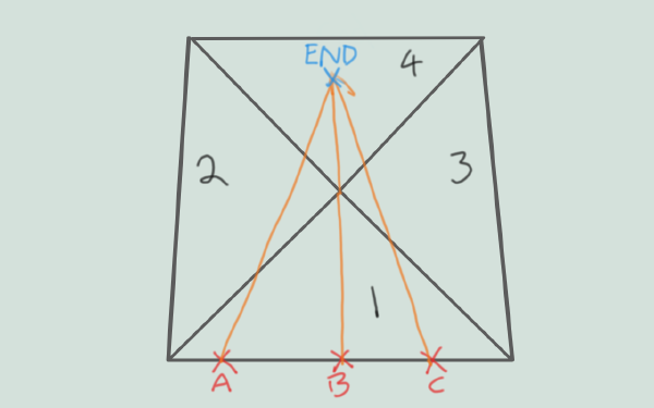
Detour, like most pathfinding libraries, uses A star or some variation of it in order to find a path from the start to the destination. The problem with A star with respect to ‘open’ navmeshes is that there are often multiple valid paths, and the optimal choice isn’t known while searching through the mesh. I tested another implementation of navmesh pathfinding and it would fail to return any result in cases where the mesh had multiple valid path options, so perhaps this isn’t such an easy problem to solve. The issue is that as shown below, the optimal next triangle to choose depends on where the current triangle was entered. At point A, 1->2->4 would be optimal, at point C 1->3->4 would be, and if the points are exactly along the lines then both would be equally optimal. My guess is that doing some kind of recursive solution to backtrack and find the ingress location is relatively expensive, and the Detour solution of finding a good enough path and then using string pulling to straighten the path is better for the majority of cases.
What this means in practice is that creating a good navmesh for detour involves creating as few polys as possible, so our grid creation, while pretty, was actually working directly against our goals. What we now want to do is satisfy the above condition without sacrificing the speed of our manual system, which will mean creating a triangulation. In addition, it’s becoming obvious that tracking the height is also counter to this goal, since it will mean creating many valid paths, so it’s possible that our end result is actually a 2D navmesh and when requesting a path for use on our map, we’ll need to add the height later. This would mean a bit of a slowdown since we’d need to figure out which triangle each point is in before doing a barycentric calculation to determine the height, so we’ll see how the results are with the heights in there as well and compare.
Delaunay Triangulations using Delaunator
Delaunator is an open source licensed library that can take a set of 2D points and create a
delaunay triangulation out of them.
Delaunay triangulations are quite nice because they “maximise the minimum angle of all the triangles” which generally produces
visually pleasing meshes that avoid very narrow triangles where they can.
The original delaunator and its documentation are in javascript, but there is a c++ port that we can easily paste into our project in a new file Delaunator.h.
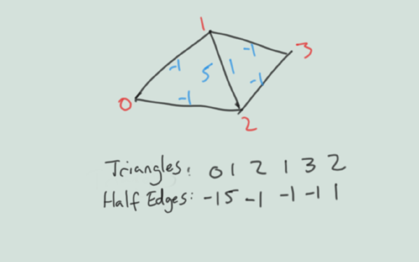
The indexing system for Delaunator is to track
- Coords: the vertices in the triangulation
- Triangles: the indices for each triangle
- HalfEdges: the index of the equivalent edge in the adjacent triangle, or -1 if this is the border.
We can convert the delaunator output with the following snippet. Note that delaunator uses doubles, this can be important even
if the end result is converted to floats because floating point error can cause issues detecting colinear points. I have a struct
defined here FPCGDelaunayTriangulation to hold the coords, triangles and halfedges since they’re generally passed around as a group.
void URegionDistribution::GenerateTriangulation(UPARAM(ref) TArray<FVector2D>& inPoints, UPARAM(ref) FPCGDelaunayTriangulation& Triangulation)
{
	std::vector<double> TestCoords;
	TestCoords.reserve(inPoints.Num() * 2);
	for (auto& V : inPoints)
	{
		TestCoords.push_back(V.X);
		TestCoords.push_back(V.Y);
	}

	delaunator::Delaunator Delaunator(TestCoords);

	Triangulation.Coords.Reset(Delaunator.coords.size() / 2);
	for (int32 i = 0; i < Delaunator.coords.size() / 2; i++)
	{
		Triangulation.Coords.Add(FVector2D(Delaunator.coords[2 * i], Delaunator.coords[2 * i + 1]));
	}
	Triangulation.Triangles.Reset(Delaunator.triangles.size());
	Triangulation.HalfEdges.Reset(Delaunator.triangles.size());
	for (int32 i = 0; i < Delaunator.triangles.size(); i++)
	{
		Triangulation.Triangles.Add(Delaunator.triangles[i]);
		Triangulation.HalfEdges.Add(Delaunator.halfedges[i]);
	}
}
Slicing the triangulation into tiles of convex polys
This was significantly more code than I anticipated, and I don’t think I’ve handled some edge cases. I would encourage interested parties to have a look at the sample project for the gritty details, I’ll lay out the approach in general terms here.
The first thing to note is that I’m not going to worry about the extremely large number cases which I would describe as anything with more than 100,000 triangles. To get good results with larger datasets it’s critically important to design algorithms that don’t bloat memory by storing maps or make multiple passes over the same data (where possible). If I can get the navmesh to generate in under a second then I’m already happy, and further reductions are going to give rapidly diminishing returns.
Slicing Process Overview
To slice up the triangulation we’re going to go through each triangle and add the verts we care about to an array and one of two different maps so that we can track when polys need to share a vert. The maps will be for the internal vertices, which will be the index in the triangulation -> the index in our array, and the halfedge index in the triangulation -> the index in our array. We also need to check to see if any of the corners are inside the triangle.
The only tricky part here is mapping a halfedge to a vert. This might seem odd, but it neatly encapsulates the different cases we can have:
Handling edges
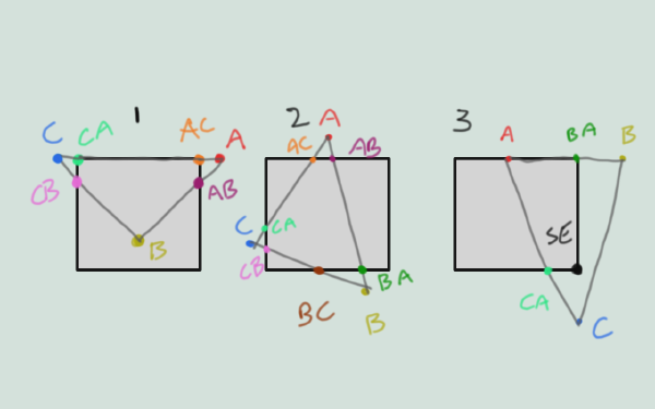
In general, the half edge going outside to in is the one used to hold a point where there is any doubt. Doing an intersection test of the triangle segment against each border segment will yield the desired points most of the time, and for cases like #2 above taking the closest intersection will work.
In case 1 AC/CA segment lies on the border, so AC and CA will both the the corners, but an intersection test isn’t going to work. So the edge test needs to be:
- If the halfedge is already in the map, then return what’s there. Set both directions (AB and BA)
- If the halfedge is colinear with one of the segments:
- If one point is on the segment, move the other to its closest corner and return that
- If two points are on the segment, do nothing and return since those points can be used as-is
- If no points are on the segment but they are on different sides of the tile, set both to corners
- If no points are on the segment and they are on the same side of the the edge do nothing and return
- Do intersection tests between halfedge and each boundary segment for both directions
In case 2 the poly will have 6 verts, which is the maximum, with each half edge corresponding to a different point on the tile border.
This means we can set TileParams.nvp to 6 and it will be safe, if inefficient for some tiles.
In case 3 the triangle contains one of the corners, so for placing points later on we’ll need to track which tile border each point is on so that when two subsequent points don’t share an edge, we can insert the corner(s) to connect them.
Once we’ve processed all the points and edges of the triangle we can place it as a poly in the navmesh by walking around the points we found, placing corners as available and needed. Since the total set of triangles to be converted to polys isn’t yet known, mark adjacent polys using the triangulation index.
Once all triangles are done, convert the triangulation index to the poly index using the polymap, and then copy data into the
TileParams
PolyMap = {}
InternalVertMap = {}
HalfEdgeVertMap = {}
TempVerts = []
TempPolys = []

for triangle in Triangulation.Triangles:
    PointsToPlace = []
    # If all points of the triangle are on the wrong side of the same tile boundary then
    # it's not possible for there to be any intersection with the bounds.
    if AllPointsAreOnOneSide(triangle, bounds):
        return 0

    # Determine the status of each point;
    #   - Point is on an edge of the bounds
    #   - Point is a corner of the bounds
    #   - Point is inside the bounds
    #   - Point is outside the bounds
    # If the point is not outside, add the vert to our temp array of vertices and store the mapping from the triangulation coord index
    # to the temp array index in the InternalVertMap
    A = ClassifyPoint(triangle.FirstPoint)
    B = ClassifyPoint(triangle.SecondPoint)
    C = ClassifyPoint(triangle.ThirdPoint)

    # If no points are outside, place the triangle
    if A.Type != External and B.Type != External and C.Type != External:
        PlacePoints([A,B,C])

    # Check to see which corners of the tile are inside this triangle
    Corners = ClassifyCorners()

    # Create a quad for the whole tile in TmpVerts and TmpPolys if
    # all four corners are inside this triangle
    if AllCornersWithinTriangle():
        MakeQuad()

    AB,BA = ClassifyEdge(AB)
    BC,CB = ClassifyEdge(BC)
    CA,AC = ClassifyEdge(CD)

    # If there's 2 valid verts that could mean there's a triangle edge along the
    # tile boundary that points away from the tile, which we can ignore
    count = GetNumValidVerts(A,B,C,AB,BA,BC,CB,CA,AC,Corners)
    if count >= 3:
        # Place the valid points that we got along with any corners
        # we can use
        PlacePoints([A,AB,BA,B,BC,CB,C,CA,AC],Corners)

# fix up the adjacencies, since we used the triangulation numbers
for poly in TempPolys:
    for edge in poly:
        if not MeshBorder(edge) and TilePortal(edge):
            edge = PolyMap[Edge]

# Copy data into detour tile params
memcpy(TempPolys, polys)
memcpy(TempVerts, verts)
Point and Edge Classification
This is the easiest part of the process. Each point needs to be marked with exactly where it is in the tile, or if it’s outside.
If the point isn’t External then it gets added to the VertMap for use.
def ClassifyPoint():
    if PointIsCorner:
        # NE|SE|SW|NW
	AddPointToVertMap()
        return Corner
        # N|S|W|N
    if PointIsOnBoundary:
	AddPointToVertMap()
        return Boundary
    if PointIsInside:
	AddPointToVertMap()
        return Internal
    if PointIsOutside:
        return External
Edge classifications were discussed earlier and need to be handled in the correct order because intersection tests on colinear segments will give odd results.
def ClassifyEdge():
    # if this half edge has already been assigned a vert in our map then use that
    # also check if the reverse pair for this edge is available and use that if it's there
    e1 = None
    e2 = None
    if halfedge in halfedgevertmap:
        e1 = halfedgevertmap[e1]
    if adjacentedge(halfedge) in halfedgevertmap:
        e2 = halfedgevertmap[e2]
    if e1 or e2:
        return e1,e2

    # if it lies along the boundary with both points on the edge, both the points
    # in the segment will already be valid and we can return immediately
    if InternalBoundarySegment():
        return None,None

    # check the edge to see if it's colinear with any boundary edges.
    #  - If it is, and one point is on the edge while the other is outside
    #     -  Set the edge originating from the outside point to the corner vert
    #  - If it is, and both points are outside the bounds on different sides
    #     -  Set the edges to their closest corners
    #  if either of these tests returned a usable vertex then return
    if ColinearCheck(e1, e2):
        AddToHalfEdgeVertMap(e1, e2)
        return e1,e2

    # Do edge-boundary intersection tests.
    # Assign an edge to the intersection point when it's traversing from outside the bounds
    # to inside. Particularly important when an edge intersects with two boundaries
    if IntersectingEdgeCheck(e1,e2):
        AddToHalfEdgeVertMap(e1, e2)

    return e1,e2
Placing Points
Once we have a list of all the points in order, we can walk around them. The tricksy edge case that needs handling is the case where we go in one edge and out another edge, and need to connect using corners. The reason for the forward and reverse direction check can be seen in the below case:
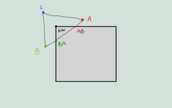
The Points array will have two entries: AB and BA, and the corners will have NW set. So the current point
is AB on the North edge, the next is BA on the West edge. They’re on different edges but we have a corner
that connects them, so we place the corner NW. Then our next point is BA and after it is AB again! So without
a check to make sure we don’t place corners connecting both AB->BA and BA->AB we’ll end up with a broken poly.
Note that this means that for each point, it’s needed to store which point/edge on the triangle it’s derived from, as well as where in the tile its located and its index in the new Vert array.
def PlacePoints(Points, Corners):
    for Current in Points:
        # Wrap around from the end to the start when getting the next point
        Next = GetNextPoint()
        TempPolys[VertIndex] = Current.Index

        # If current and next point are both derived from edges, but they don't share a common edge,
        # and they're not the forward and reverse direction of the same edge (eg Current = AB and Next = BA)
        # then we need to insert the current vert and then corners that connect the two edges
        if (ConnectableEdges(Current, Next):
            PlaceCorners()
        else:
            # determine if we're on the edge and should be a portal to another tile, or if
            # we're adjacent to another poly within this tile. If adjacent, use the triangulation
            # numbering and we'll fix it up later
            border = GetAdjacency(Current, Next)
            TempPolys[BorderIndex] = border
Further possible optimisations and remaining issues
I think I could skip the conversion of adjacency values from triangulation to polys by using the higher of the two triangle indices to be “responsible” for inserting adjacency for both it and its neighbour. We lose the information of which edge of the triangle is which edge of the poly when we move on to the next triangle so we’d have to search for the right edge, but this might be OK given it’s a maximum of 6 edges.
If I’m being generous this would reduce the complexity from O(2n) to O(n) where n is the number of triangles.
Results and conclusions
If we throw artistic caution to the wind and draw
- Colored segments for edges that connect in the different tile portal directions
- White segments for edges that connect to another poly within the tile
- Purple numbers for the vert indices within the tile
- White numbers for each triangle in the triangulation
- Orange numbers for each poly in each tile
- Green numbers for poly adjacency
We get this abomination which contains just about everything needed to debug what’s going on.
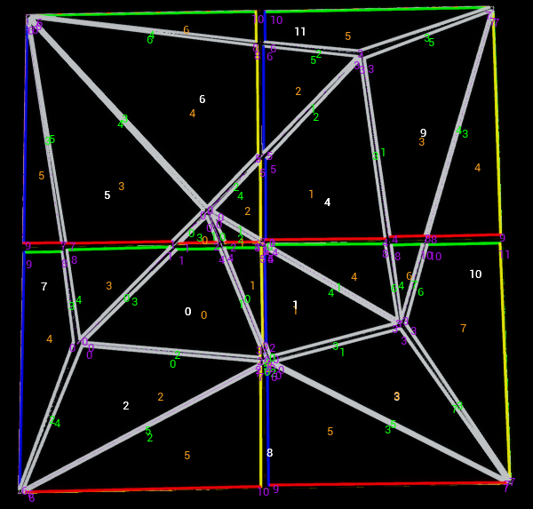
Of course the standard debug draw is also available, but adjacency issues in particular often won’t appear there.
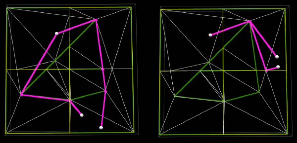
We can now do a pathfinding test or two and see what the results look like. I’ve also added the option to mark triangles
in the source triangulation as impassable, so we can have some basic obstacles. For these examples I’ve set 0,1 and 4 to
impassable using polyAreas and polyFlags.
Note that this is currently only 2D, I’ll add heights in the next post - this one is already longer and more code than I expected.
The results are actually quite poor in a lot of cases, because A star is still not taking anywhere near the optimal path. I’ve set the inner triangles to be impassable, so this is actually kinder to the implementation than some of our grid tests.
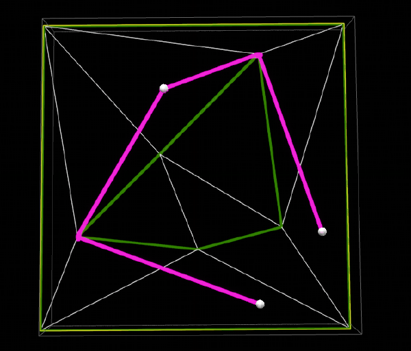
On a more positive note, if we create the triangulation without splitting it into pieces then the results get a lot better. This indicates that similar to the grid series, if we reduce the number of tiles/polys then the results improve markedly.
Next Steps
First we should add the heights. This may help the A star heristic in determining which adjacent poly is closer to the goal.
There is a note on the recast github that small triangles next to large triangles can cause issues, which might be why the NavMesh
Generation options in UE4 includes Merge Region Size which by default merges any region below 400 (square units presumably) into a
larger neighbour, and Min Region Size which can outright discard regions that are extremely small (though this is disabled by default).
Some of our polys could very clearly be combined to create larger convex hulls,
which might assist the algorithm as each path would need to take less steps. To really understand this I’ll need to see whether
a star is running over the poly convex hulls or their constituent triangles. If it’s the latter, it could be harder to fix, and
unfortunately I think that is the case.
There’s a potential bug where points that are closer to each other than the CellSize end up on top of each other and we end up with
zero area polys/triangles. This almost happens in our example where one of the points is very close to the tile border. If we’re adding
a step that merges small areas with large ones, this could be fixed in the same step.
There’s a PR upstream that was merged a long time ago that might help with these issues here which doesn’t appear to be merged into the UE4 fork of Detour.
Doing it without tiles, or with few tiles
The number of verts and polys are both an int, so it’s possible we can create a giant single tile mesh as well. What might need testing
for this case is whether point-in-triangle tests are slow, since without the tiles to bound which polys a particular point might lie
within. This seems to be handled within dtNavMeshQuery::findNearestPoly and there’s a note that searching more than 128 polys might
return an invalid result since there’s a fixed size buffer.
This also might explain what the default query extent in
Project Settings -> Navigation System -> Agents is used for - The query finds polys that intersect with the extent, and does convex
hull containment tests on the polys that do. The tiles are used as an earlier filter, so removing them may have a negative effect on
performance.
In addition, this query will flow through to dtNavMeshQuery::quryPolygonsInTile which is very obviously able to use a bounding
volume tree if available to speed up the search. We currently have TileParams.buildBvTree = true so with a little luck, having few tiles
will not be the huge performance penalty it first appeared.
