Efficiently Making Navmeshes for Procedural Worlds in Unreal 4
This previous post lays the groundwork introducing Detour, Unreal, the problem space and an initial solution, start there if you’re new to making your own navmeshes in Unreal.

Refactors and Debug
The existing code needs a bit of cleaning up before we move on, and it’s likely we’ll want our own debug draw+dump method so we can see what’s going on as we create each tile. The built in debug draw for navmeshes is useful for seeing that the end result is roughly correct, but it won’t tell us if we’ve messed up a portal direction, or if we completely mess up a poly definition we’ll see absolutely nothing.
The first step is to make it a bit easier to peek into dtNavMeshCreateParams and see where any given vector is by
converting from the cellsize * short notation in -XZ-Y coordinates back to Unreal.
FVector AManualDetourNavMesh::GetVector(dtNavMeshCreateParams& TileParams, unsigned short Index)
{
	if (Index >= TileParams.vertCount)
	{
		UE_LOG(LogManualNavMesh, Warning, TEXT("Requested vector %d from detour but only %d vectors available"), Index, TileParams.vertCount);
		return FVector::ZeroVector;
	}

	return FVector(
		TileParams.verts[3 * Index] * TileParams.cs * -1.f - TileParams.bmin[0],
		TileParams.verts[3 * Index+2] * TileParams.cs * -1.f - TileParams.bmin[2],
		TileParams.verts[3 * Index+1] * TileParams.ch + TileParams.bmin[1]
	);
}
When drawing a discretised 2D space like a navmesh, we’re often interested in how each poly defines each edge, which means that each internal edge will be drawn twice - once by each poly. So in order to see both edges we’ll move each edge towards the centre of its poly by a small amount.
FVector AManualDetourNavMesh::GetPolyCentre(dtNavMeshCreateParams& TileParams, unsigned short Index)
{
	if (Index >= TileParams.polyCount)
	{
		UE_LOG(LogUPCGTNavMesh, Warning, TEXT("Requested centre of poly %d from detour but only %d polys available"), Index, TileParams.polyCount);
		return FVector::ZeroVector;
	}

	int32 Count = 0;
	FVector Ret = FVector::ZeroVector;
	int32 Start = Index * TileParams.nvp * 2;
	for (int32 i = Start; i < Start + TileParams.nvp; i++)
	{
		if (TileParams.polys[i] == RC_MESH_NULL_IDX)
			break;
		Ret += GetVector(TileParams, TileParams.polys[i]);
		Count++;
	}

	Ret /= (float)Count;
	return Ret;
}
void AManualDetourNavMesh::MoveToCentre(FVector& InVector, const FVector Centre, float Distance)
{
	FVector Dir = (Centre - InVector).GetSafeNormal();
	InVector += Dir * Distance*2.f;
}
Finally, we’ll define some colors to indicate different types of edges for use when drawing:
FColor AManualDetourNavMesh::GetEdgeDebugColor(unsigned short EdgeCode)
{
	static FColor BorderColor = FColor::Cyan;
	static FColor InternalEdgeColor = FColor::Silver;
	static FColor WestPortalColor = FColor::Red;
	static FColor EastPortalColor = FColor::Green;
	static FColor SouthPortalColor = FColor::Blue;
	static FColor NorthPortalColor = FColor::Yellow;

	switch (EdgeCode)
	{
	case 0x8000:
		return WestPortalColor;
	case 0x8001:
		return NorthPortalColor;
	case 0x8002:
		return EastPortalColor;
	case 0x8003:
		return SouthPortalColor;
	case RC_MESH_NULL_IDX:
		return BorderColor;
	default:
		return InternalEdgeColor;
	}
}
Now we can build our debug draw function relatively easily. The only thing we really need to take care of is making sure
we wrap around the polygon correctly. The key thing to remember is there can be can be up to nvp vertices in a given
polygon, and if there’s less than that the remaining indices will be RC_MESH_NULL_IDX, so we need to iterate until we
either hit nvp or a null mesh index. Technically for our grid this won’t be an issue since all polys will have 4 vertices,
but if we later move onto more complex topologies this will be needed. We need a new property on our class DebugThickness
so that we can set it high enough to see the lines at whatever scale you’re working at.
void AManualDetourNavMesh::DebugDrawTileParams(dtNavMeshCreateParams& TileParams)
{
	static FColor VertexColor = FColor::Purple;

	for (unsigned short i = 0; i < TileParams.polyCount; i++)// *TileParams.nvp * 2; i += TileParams.nvp * 2)
	{
		int32 PolyStart = i * TileParams.nvp * 2;
		FVector PolyCentre = GetPolyCentre(TileParams, i);

		for (int32 j = 0; j < TileParams.nvp; j++)
		{
			// First vert index for the edge
			unsigned short Ind1 = TileParams.polys[PolyStart+j];

			// If current vert is null we can stop
			if (Ind1 == RC_MESH_NULL_IDX)
			{
				break;
			}

			// Second vert index for the edge, wrap back around at both the end of the poly and
			// if the next index is null.
			unsigned short Ind2 = (j == TileParams.nvp - 1 || TileParams.polys[PolyStart+j+1] == RC_MESH_NULL_IDX) ? TileParams.polys[PolyStart] : TileParams.polys[PolyStart+j+1];

			FVector V1 = GetVector(TileParams, Ind1);
			FVector V2 = GetVector(TileParams, Ind2);

			unsigned short EdgeCode = TileParams.polys[PolyStart + TileParams.nvp + j];
			FColor EdgeColor = GetEdgeDebugColor(EdgeCode);

			UE_LOG(LogUPCGTNavMesh, VeryVerbose, TEXT("Edge %d of poly %2d EdgeCode %4hu (%2hu)-(%2hu) :: %s - %s"), j, i, EdgeCode, Ind1, Ind2, *V1.ToCompactString(), *V2.ToCompactString());

			MoveToCentre(V1, PolyCentre,DebugThickness);
			MoveToCentre(V2, PolyCentre,DebugThickness);
			DrawDebugLine(GetWorld(), V1, V2, EdgeColor, true, 999.f, 0, DebugThickness);
		}
	}
}
Subdividing the grid
The guts of the change to our previous work lie in improving from a single poly per-tile to having many. The current tile creation
code we didn’t have to handle the case where one poly linked to another poly within that tile, which fortunately is less esoteric
than the portals code covered earlier. While we’re there, we’ll add a new function similar to GetVector that lets us easily set
a vert within Detour using an Unreal FVector.
void AManualDetourNavMesh::SetDetourVector(unsigned short* verts, const FVector V, unsigned short Index, dtNavMeshCreateParams& TileParams)
{
	const float ncsinv = -1.0f / TileParams.cs;
	const float chinv = 1.0f / TileParams.ch;
	verts[Index * 3] = (unsigned short)(FMath::FloorToInt((TileParams.bmin[0] + V.X) * ncsinv));
	verts[Index * 3 + 1] = (unsigned short)(FMath::FloorToInt((V.Z * TileParams.bmin[1] * -1.0f - TileParams.bmin[1]) * chinv));
	verts[Index * 3 + 2] = (unsigned short)(FMath::FloorToInt((TileParams.bmin[2] + V.Y) * ncsinv));
}
We want to subdivide our tile based on the number of cells, rather than just dividing a float. Otherwise we might end up with single cell gaps between tiles or polys.
	GridSubdivisions = GridSubdivisions <= 0 ? 1 : GridSubdivisions;

	// We want [GridSubdivisions] quads on each row so we need one more vertex at the end
	unsigned short RowLength = GridSubdivisions + 1;
	TileParams.vertCount = RowLength * RowLength;

	// Each quad will be a poly
	int MaxPolys = GridSubdivisions * GridSubdivisions;

        // Divide our Tile up evenly into cells
	unsigned short CellsInTile = FMath::FloorToInt((Bounds.Max.X - Bounds.Min.X) / TileParams.cs);
	unsigned short CellsInSubdiv = CellsInTile / GridSubdivisions;

	// Vertices per polygon
	TileParams.nvp = 4;
We can now add our verts for the tile.
	for (int32 j = 0; j < RowLength; j++)
	{
		for (int32 i = 0; i < RowLength; i++)
		{
			SetDetourVector(verts, FVector(Bounds.Min.X + i * CellsInSubdiv * TileParams.cs, Bounds.Min.Y + j * CellsInSubdiv * TileParams.cs, 0.f), j * RowLength + i, TileParams);
		}
	}
Now we need to add the grid structure to our polys.
- Quads at the edge of the tile need to have either a portal to the next tile or a border edge
- Other edges should be internal links to other quads
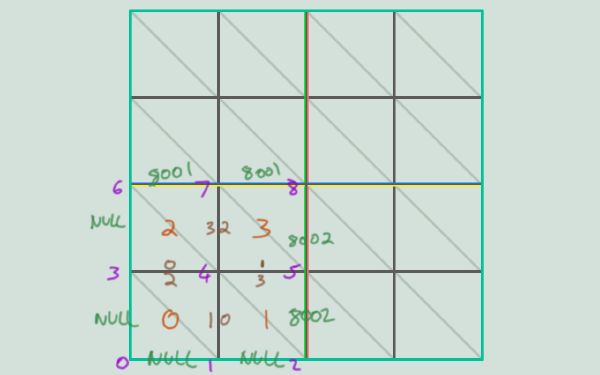
So our bottom left tile in the above image will have polys:
//       |    poly 0           |        poly 1       |          poly 2     |      poly 3         |
//       | verts |  edges      | verts |    edges    | verts |    edges    | verts |    edges    |
polys = [ 0 3 4 1 NULL 2 1 NULL 1 4 5 2 0 3 8002 NULL 3 4 6 7 NULL 8001 3 0 4 5 7 8 2 8001 8002 1 ]
	unsigned short* polys = (unsigned short*)FMemory::Malloc(sizeof(unsigned short) * MaxPolys * TileParams.nvp * 2);
	memset(polys, 0xff, sizeof(unsigned short) * MaxPolys * TileParams.nvp * 2);

	for (int32 j = 0; j < GridSubdivisions; j++)
	{
		for (int32 i = 0; i < GridSubdivisions; i++)
		{
			unsigned short PolyIndex = (i + j * GridSubdivisions)*TileParams.nvp*2;

			polys[PolyIndex]     = j * RowLength + i;
			polys[PolyIndex + 1] = (j + 1) * RowLength + i;
			polys[PolyIndex + 2] = (j + 1) * RowLength + i+1;
			polys[PolyIndex + 3] = j * RowLength + i+1;

			if (i == GridSubdivisions - 1)
			{
				if (TileParams.tileX == 0)
				{
					// Mesh Border
					polys[PolyIndex + 6] = RC_MESH_NULL_IDX;
				}
				else {
					// Tile Border to another tile
					polys[PolyIndex + 6] = 0x8000;
				}
			}
			else {
				// Subdiv border to another poly
				polys[PolyIndex + 6] = (i+1) + j*GridSubdivisions;
			}

			if (j == 0)
			{
				if (TileParams.tileY == TileCount - 1)
				{
					polys[PolyIndex + 7] = RC_MESH_NULL_IDX;
				}
				else {
					polys[PolyIndex + 7] = 0x8001;
				}
			}
			else {
				polys[PolyIndex + 7] = i + (j-1)*GridSubdivisions;
			}

			if (i == 0)
			{
				if (TileParams.tileX == TileCount - 1)
				{
					polys[PolyIndex + 4] = RC_MESH_NULL_IDX;
				}
				else {
					polys[PolyIndex + 4] = 0x8002;
				}
			}
			else {
				// Subdiv border to another poly
				polys[PolyIndex + 4] = i-1 + j*GridSubdivisions;
			}

			if (j == GridSubdivisions - 1)
			{
				if (TileParams.tileY == 0)
				{
					polys[PolyIndex + 5] = RC_MESH_NULL_IDX;
				}
				else {
					polys[PolyIndex + 5] = 0x8003;
				}
			}
			else {
				// Subdiv border to another poly
				polys[PolyIndex + 5] = i + (j+1)*GridSubdivisions;
			}
		}
	}
With that and the boilerplate from the previous post we should have a working subdivided grid on each tile, but still without any heights.

Path testing oddities
Before adding the heights there’s some interesting results from testing that are worth mentioning. I split my testing into two parts so that I could build the manual navmesh with one editor button and run a test that searches for a random path with another, which let me run a large number of visual tests on command on both the manual navmesh and the recast generated navmesh.
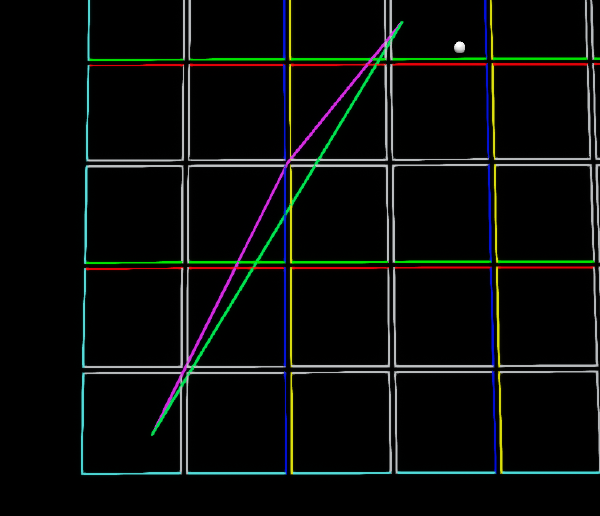
The test itself results in a green line being drawn from the start to the end, while purple lines are drawn between each
consecutive point in the path that is returned by FindPathToLocationSynchronously if any of four conditions are met:
- The Start location is not the same (tolerance 0.001f)
- The End location is not the same (tolerance 0.001f)
- The path is not valid
- The path has multiple segments
Here’s an example failed result:
Running a batch of 100 tests I saw up to a 30% failure rate, with the result looking like a bit of a jumbled mess:

Most of these failures aren’t very serious, with only small deviations from the optimal path, but some of them are very clearly doglegging for seemingly no reason. This is apparently a known but infrequently encountered issue with Unreal/Detour with the suggested fix being to include more obstacles on the map and avoid large, open, flat locations. I haven’t looked in detail at why this occurs in Detour, but a likely answer is that it is quite difficult to determine the optimal path through a triangulation. I think Detour makes a best effort at choosing a path through a set of polygons, then performs a string pulling in order to optimise the result as much as possible, but if the wrong polygons were chosen in the initial search then the string pulling won’t be able to pull the path into a completely straight line.
There’s an old answerhub question that might have been along these lines as well.
Unreal Fast Noise Plugin
We can use the fast noise plugin available on github to generate some simple noise
in order to demonstrate the use case for manual navmeshes. You can install the plugin by cloning it into the Plugins folder in
the root of your project, then adding PrivateDependencyModuleNames.AddRange(new string[] { "UnrealFastNoisePlugin" }); to
your project’s build.cs.
FastNoise exposes a function float GetNoise2D(float X, float Y) that we’ll use in both the navmesh and the world map mesh generator
to get a nice smooth terrain. The details of building a little simplex noise based grid mesh aren’t particularly novel so I
won’t go through it here, but if you’re new to procedural generation you can always check out the AWorldMap class in the
sample project. I’m using the built-in plugin ProceduralMeshComponent to create the mesh.
Adding heights from noise
We’ll use the world map instance in the level to grab the height at any given point, though these two classes will be tightly coupled so it could be either way around really. In a real project you’d want this functionality out in a plugin with interfaces to be implemented by providers of the terrain height to decouple them, but for our toy we won’t bother.
The FastNoise plugin returns noise in the range -1.0 to 1.0, I tend to change it to the 0.0 to 1.0 range because it’s simpler to
me by adding 1.0 and halving the result but it’s up to you how you want to treat it. The only important thing is that you never end up
with a height below bmin[1] because the unsigned short will end up as 65536 and your navmesh will be up in the sky.
float AManualDetourNavMesh::GetHeightAt(float X, float Y)
{
	if (SourceMap)
	{
		// GetHeightAt is doing the conversion to 0-1 range
		return Min.Z + (Max.Z - Min.Z) * SourceMap->GetHeightAt(X, Y);
	}
	return 0.f;
}
Our vert creation code changes a little to use this:
	for (int32 j = 0; j < RowLength; j++)
	{
		for (int32 i = 0; i < RowLength; i++)
		{
			float X = Bounds.Min.X + i * CellsInSubdiv * TileParams.cs;
			float Y = Bounds.Min.Y + j * CellsInSubdiv * TileParams.cs;
			SetDetourVector(verts, FVector(X, Y, GetHeightAt(X,Y)), j * RowLength + i, TileParams);
		}
	}
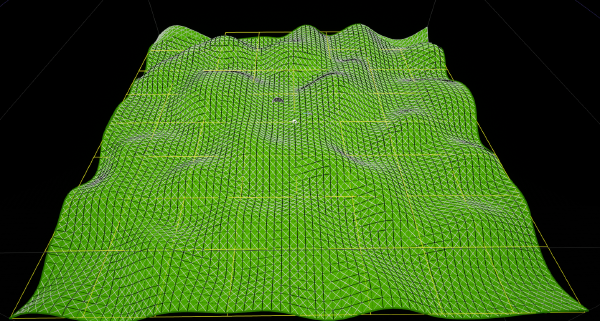
And we can easily get a nice looking result like this:
Conclusions
I played around with the settings for Recast and even with smaller cell sizes it was always simplifying the mesh quite a lot. It’s clear that the mesh doesn’t quite match the underlying geometry, though there’s almost certainly room for improvement here given a cell size of 1.0 should really be able to do better than this.
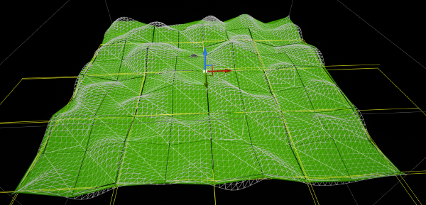
What I think is happening here is the size is simply too small, and there’s some internal scale for Recast within Unreal that impairs its ability to make small, tight meshes. By blowing up the navmesh + world to be more like the scale Unreal users would be familiar with - 2km square - the results get much better and the recast mesh is now wrapping the terrain pretty tightly. Unfortunately, as the video below shows, it’s now going to take about 6 minutes to generate our nav mesh using Recast.
I can get this down to about 30 seconds by increasing the tile size to 2048uu with 16.0f Cell Size, but this is still too long in my opinion, so I’m happy with the results of our manual creation. We’re also able to make much smaller navmeshes than recast seems to be able to deal with so for cases where the map should be packed into a small space at 1/100 scale or similar manual generation may also be useful.
Sample Project
A sample project is available at https://github.com/michaeltchapman/ManualNavMesh/
which demonstrates the ideas shown here. The BP_NavMeshDebug actor in the world has a few buttons on it that can be used to
build the manual nav mesh and run tests, the BP_WorldMap actor is responsible for creating the random terrain and has a button to
rebuild, and most of the settings for nav mesh creation are on the ManualDetourNavMesh-Default actor that will function exactly
like a recast navmesh actor if not interfered with.
Next Steps
The final part of this series will take an arbitrary surface mesh, slice it into tiles, and create a detour navmesh from that. This will give us the control we need to create truly accurate maps that match the game world in a strategy game and aren’t limited by grid accuracy.
